Since we introduced our newly developed Wheel Force Sensor at the SAE (Society of Automotive Engineers) in April this year, we have on several occasions been asked to explain why our product is far better in accuracy than those of our competitors who launched on to the market before us. The Wheel Force Sensor or WFS is a torque measurement device built into the wheelbase of an automobile that measures three directional components of forces and three components of torque associated with each directional force while a car is on the move. Our WFS has an accuracy of 0.1%, which is 10 times better than the equivalent products introduced by our competitors
This accuracy is not necessarily extraordinary compared to our other force measurement or weighing instruments, but due to the harsh environment a car faces while it travels along a road and the complexity of the 6 component measurement, we have chosen 0.1% accuracy rather than the 0.01% or better usually offered by our weighing instruments. The 0.1% accuracy allows for detection of the effects of rolling friction of the tire on the road, which in turn makes the analysis of the effect on a tire in relation to the energy being transferred from the tire to the car possible. In other words, the 0.1% accuracy is a must if one wants to analyze the effects of a tire or energy loss through a tire. A device with only 1% accuracy cannot observe these effects because the effects of rolling friction are in the order of 1%.
|
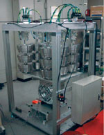
Attached Wheel Force Sensors |
In one instance an engineer working for an automobile company who evaluated the WFS reported that it showed incorrect results, or results differing between the right and left wheels, and cast a doubt on the accuracy of our device. Since they used two WFS's on both of the front wheels, we suggested that the WFS's be alternated between the right and left wheels. To the bewilderment of the engineer of the automobile company, the same results were generated and the right and left wheels showed different results, which would only be possible if both wheels were unbalanced for some reason. Incidentally, this situation proved the accuracy and benefit of our 0.1% accurate WFS.
This story reminded me of an experience I had in 1986 when we launched the FV Platform Scale Series (the first generation of our HV or FG Platform Scales). "It is impossible to use plastics for industrial applications!" James Glidden proclaimed when Yutaka Murata, our head of weighing R&D, brought the FV Platform scale to A&D Engineering, our subsidiary in the US. "A more rugged kind of scale is needed for a harsh factory environment," he added. When Murata-san removed the weighing pan and showed it to Glidden-san, his tone became even harsher. "Aluminum load cells have absolutely no chance!"
Despite the advice from the outspoken, experienced salesman and scaleman (I always respect Glidden-san's straight-forward and insightful comments), we went ahead and launched the FV scales. We received similar reactions from our scale dealers and had some difficulties as Glidden-san had said we would. However, we began hearing some interesting comments. "It doesn't break. It keeps working. It has dents here and there. I knocked over the meter-head but the unit still works, and it is accurate." As word spread, our sales increased, and the FV gained a strong hold in the industry.
In the case of the FV Series we had chosen aluminum as the spring element of the load cell because of its economical cost. We wanted to replace the then dominant mechanical dial scales with the FV Series, and for that we had to competitively price the FV. It was a very aggressive strategy, which nobody had attempted before. We had to do everything possible to lower the manufacturing costs by employing the most cost-effective materials, such as aluminum and plastics, while at the same time overcoming their weaknesses using our unique and innovative mechanical and electronic development ideas.
At that time, we had one unique approach to the design of a load cell. The most fundamental factor that dominates the performance of a load cell is the design of the strain (amount of distortion) in relation to the ultimate yield point of the spring element, that is, where it stops returning to the original position when the force is removed. Strain is defined as dl/l where l is the original length and dl is the change in length or the amount compressed or stretched. It means the rate of distortion applied to an element. A spring element when distorted should go back to the original form when the strain or force causing the distortion is removed. This is only the case if it is deflected below the ultimate yield point or elasticity limit, beyond which part of the distortion will remain and affect the condition of the element. When a metal has a lower ultimate yield point, it stops acting as an elastic material faster and easier. Aluminum is considered to be such a material.
In normal cases the capacity of a load cell is designed to be one half of the ultimate yield point, which results in the rated output specifications of around 3 mV/V. This means that if this load cell receives a force twice its rated capacity, it is likely to be permanently damaged because its distortion exceeds the ultimate yield point.
Further influential factors regarding the physical design of a load cell are the gauges themselves, backing materials and the glue that is used. The characteristics of these materials in terms of elasticity and hysteresis will directly affect the accuracy of the load cell. However, the smaller the distortion applied to the spring element including the gauges, the backing materials and the glue, the better the load cell performance will be in terms of repeatability and linearity. Besides if a load cell works at a lower strain level, it is less susceptible to damage by shock or overload.
Unlike the conventional design of a load cell at that time, A&D chose to use a lower strain or lower rated output of 1.5 mV/V. By doing so we were able to increase the safety factor by a factor of 2, which resulted in an extremely robust FV Platform Series model. However, this in turn required higher sensitivity and accuracy of the electronic circuitry design. More specifically, the amplifiers and analog to digital converters had to work accurately in below microvolt range, avoiding the influences of thermal effects as well as external noises and disturbances, and on top of all this, they had to be cost-efficient.
"Challenging accuracy in measurement has been the norm for A&D since the foundation of our company," says Mr. Furukawa. Our expertise in low voltage measurement electronic circuitry designs has brought overall performance and accuracy of products to a higher level. He adds, "We even had to design a tool for testing the accuracy of our high-speed Digital to Analog converter which was used for electron beam lithography back in the 1980's. Accuracy in measurement is, and will no doubt remain to be, our core competence."
We had to develop our own tools, a three-dimensional dead weight calibrator for the calibration of the WFS as well as our own unique Modeling Method where the calibrator acquires data and extrapolates 6 components by manipulating the polynomial matrix calculations. In addition to the 0.1% accuracy, the WFS sends measured data at the high-speed response time of 1 millisecond. These state-of-the-art specifications will generate valuable data making up-to-now unobserved phenomena visible, enhancing car design and leading it into a new and highly advanced stage. By that time, we foresee that the 0.1% resolution WFS will be the leading force in automobile torque measurement.
|
|
A three-dimensional dead weight Calibrator |
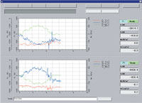
WFS Display Screen
Click picture for Larger image |
You may address any comments concerning this editorial by email to Mr. Eto
Index of Mr. Eto's other articles