Product
Weighing
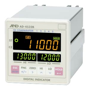
| AD-4532B | ||||||||||||||||||||
| Digital Indicator for Strain Gauge Sensors | ||||||||||||||||||||
|
||||||||||||||||||||
|
|
||||||||||||||||||||
| Features | ||||||||||||||||||||
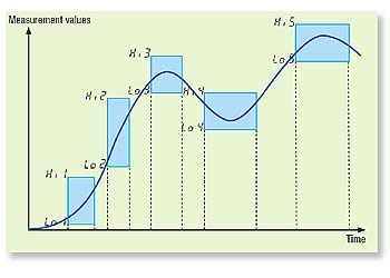
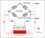
Highly visible easy-to-read display 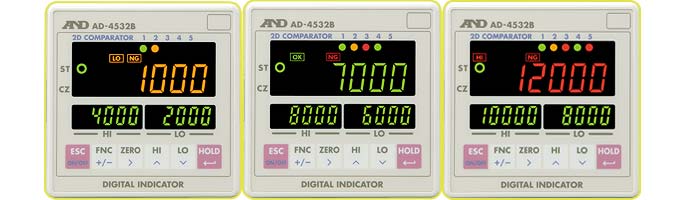 In addition to a simple comparison of the upper/lower limit, the AD-4532B is equipped with a 2D comparator function that shifts between the upper/lower limit in five levels using a time control or an external signal. |
||||||||||||||||||||
|
||||||||||||||||||||
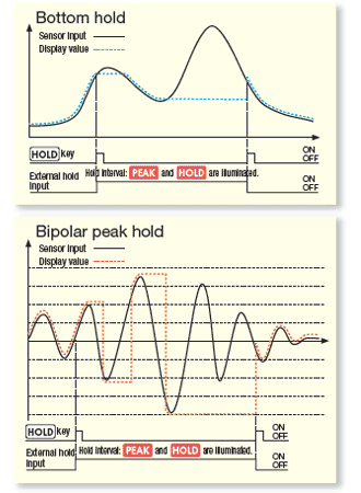
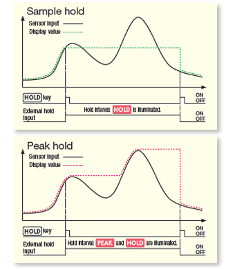
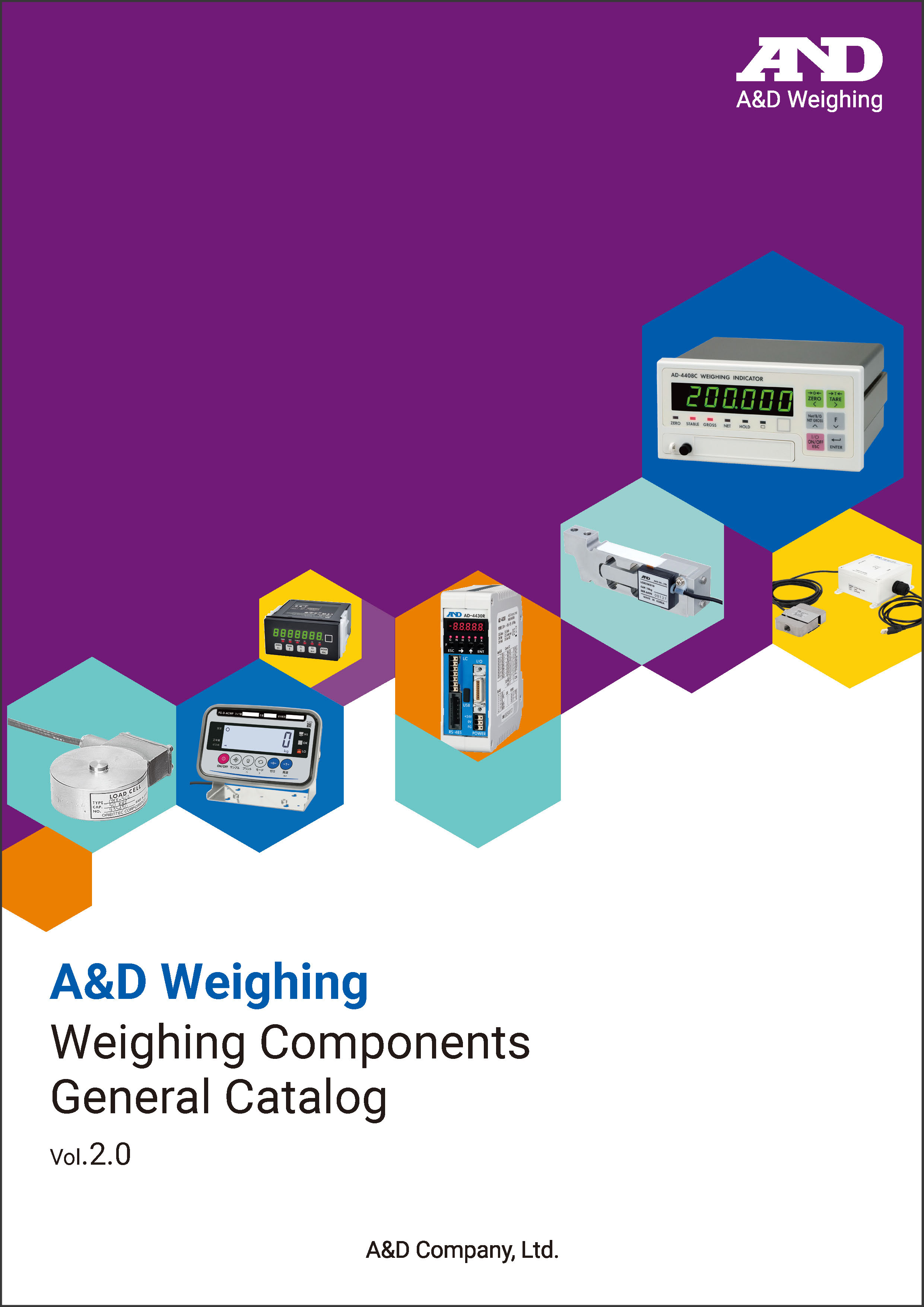
*1 Analog-to-digital conversion *2 Digital-to-analog conversion The digital span calibration function makes it possible to perform a calibration by entering the rated output (mV/V) of the sensor using the numeric keys. This function is useful when an actual load cannot be applied. The display, the comparator output and the D/A voltage output can be latched (data output hold). If bouncing of the comparator value occurs repeatedly near the upper/lower limit, a heavy burden will be placed on the relay circuit and other parts. To prevent this, the AD-4532B has a function to set the hysteresis width and time.  |
||||||||||||||||||||
| ||||||||||||||||||||
| The AD-4532B comes equipped with an analog amplifier voltage output (±10V), a D/A analog voltage output (±10V), a comparator output and a Modbus-RTU input/output. In addition, we offer an optional BCD output, RS-232C input/output, D/A analog voltage/current output (±10V / 4 to 20mA) and Ethernet. The upper/lower limit setting, the zero compensation function and the hold function can be executed via Modbus-RTU. 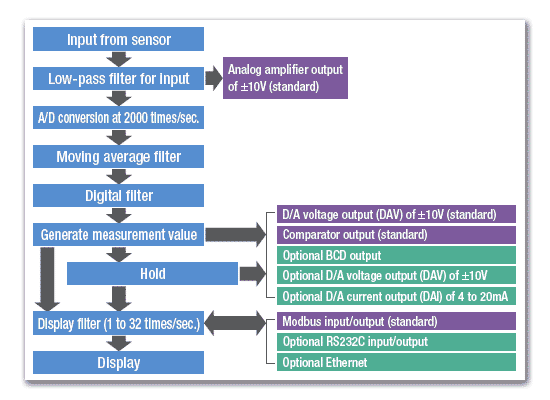 |
||||||||||||||||||||
| Videos | ||||||||||||||||||||
| Specifications | ||||||||||||||||||||
|
||||||||||||||||||||
|
||||||||||||||||||||
|
||||||||||||||||||||
| Note: Power cable is necessary. | ||||||||||||||||||||
| Options | ||||||||||||||||||||
| AD4532B-01* - BCD output (40-pin FCN connector) AD4532B-04 - RS-232C (D-sub 9 pin) AD4532B-07* - D/A analog voltage/current output (±10V and 4~20mA) AD4532B-08 - Ethernet interface (RJ-45) *Options 01 and 07 are provided with each connector. Note: Options 01, 04, 07 and 08 above cannot be used at the same time. Appearance and/or specifications subject to change for improvement without notice. |
||||||||||||||||||||
| Related Content | ||||||||||||||||||||
|