Product
Motor Simulation
Electric Vehicles (EV) and
Hybrid Vehicles (HEV)
Electric Motor Simulation for Vehicles
This system is a Hardware-In-the-Loop Simulation (HILS) system for motor controller development. The system runs in a Real-Time environment and communicates with real signals. Users can change the motor characteristics and the motor control algorithm.
Motor controller development
Motor controller development using a HILS system has the advantage that no actual motors or power supply systems are necessary, since all the target hardware is simulated virtually. A&D's motor HILS system provides virtual motor environments for developing, designing and validating motor controllers.
Features of motor HILS
A&D's Real-Time platform enables users to configure both the motor simulator and the motor controller.
- Motor simulator
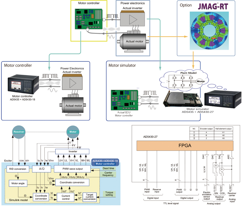
A&D's Real-Time platform has external interface boards. Actual motor signals such as PWM I/O, current sensor output, resolver carrier input, and resolver angle output (SIN, COS) can be handled in Real-Time. Our Real-Time platform utilizes FPGA, that has a low latency response which is suitable for motor simulation. - Motor controller
The motor control model is synchronized with the resolver rotation signal which means the model process does not operate in time base but angle base. This reproduces realistic behavior of motor controllers. - Motor mode
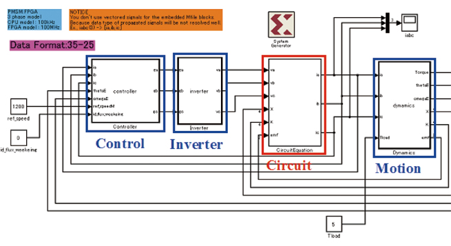
A simulation model is based on dq transformation permanent magnet synchronous motor (PMSM) model. A space harmonics model can be added on to dq transformation PMSM motor model as an option. Also, space harmonics model can be linked to JMAG™ for achieving more realistic motor simulation.
Application examples
Motor controller development
- Rapid Prototyping (RPT) application
The Real-Time Rapid Prototyping (RT-RPT) controller can be used as a motor controller unit and connected to actual motors. Since control algorithm can be changed easily with the MATLAB/Simulink™ model, interface signals to actual hardware can also be configured easily. - HILS application
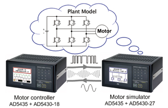
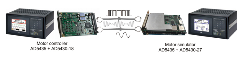
Connect an actual motor controller to a motor simulator.
Users can develop a motor controller without actual motor hardware so development of motor and controller can proceed in parallel. This also reduces the high cost of running actual motors, including facility costs, and provides a safe engineering environment. - Software-In-the-Loop Simulation (SILS) application
Use the RT-RPT controller as a motor controller unit and connect to a motor simulator.
A motor control engineer can start development and design of a motor controller at their desk without any power supply facilities or hardware. Since both the motor controller and motor simulator are working virtually, this approach is used at early phases of development. Since both systems are connected by actual physical signals, a controller prototype made from this system has seamless interface to an actual motor. (Users can connect the RT-RPT system to actual hardware without any problems)
Real-Time controller
Motor controller development
- AD5435
Main unit of the RT-RPT controller has seven option board slots for enhancing the system. - AD5430-18
Specialized board for motor control application - AD5430-27
Specialized option board for motor simulation
High precision calculation and low latency speed are realized by using FPGA.
Software package
The RT-RPT controller system comes with a control program, so the system can be used immediately. Also, users are able to modify the software such as the control algorithm and GUI interface for customization.
Included:
- Control source code (MATLAB/Simulink™ Model)
Includes MATLAB/Simulink™ add-on compiling environment (Please prepare MATLAB/Simulink™ and the ISE environment of Xilinx separately.) - GUI building software tool
Design application software (VirtualDSPConsole) is included.
Specifications
AD5435 specifications
| Memory | SDRAM 512 MB |
|---|---|
| OS | RTOS |
| Display | 5 .7 inch color TFTLCD (with backlight) |
| Operation interface | Resistive touch screen. Customizable function keys |
| I/O slots | For AD5430 series I/O board 7 slots |
| PMC interface | For A&D link or FlexRay: 1 slot (option) |
| Peripheral connections | Ethernet, 100 base - T FTP server function |
| Power specifications | AC power specification (AD5435A ) 85 to 264 V DC power specification (AD5435) 12 V (6 to 18 Vpp) or 24 V (16 to 36 Vpp) |
| Power consumption | 100 VA (AC or DC power) |
| Operation temperature range | 5 to 40°C |
| Operation humidity range | 5 to 90 % R.H. non-condensing |
| Dimensions | 318 (W) x 230 (D) x 168 (H) mm |
| Weight | About 6 .5 kg (chassis only) |
Control Board (AD5430-18) Specifications
| Resolver input | R/D converter Transformation ratio Output impedance Output excitation signal Maximum angle speed |
AU6802NI (made by Tamagawa Seiki) 0.286 / 0.5 10 Ω or less 10 kHz / 20 kHz 240,000 rpm |
|---|---|---|
| Analog input | Number of channels Signal format Sampling frequency Input range Resolution |
4 Differential signal 40kHz (maximum). Can synchronize with PWM carrier wave. ±5V 16 bit |
| PWM output | Number of control axes Output format Output voltage Carrier wave |
6 Differential (UH, VH, WH, UL, VL, WL) 0 to 5V Triangular wave, 20kHz (maximum) |
Simulation Board (AD5430-27) Specifications
| Digital input | Input level Number of channels Resolution Response Number of channels |
TTL (Single end) 7 20 ns 9 ns 4 |
|---|---|---|
| Digital output | Output level Number of channels Resolution Response Number of channels |
TTL (Single end) 9 20 ns 12 ns 9 |
| Analog output | Output level Number of channels Output range Output current Output impedance Resolution Sampling Conversion |
Differential 5 ±12 Vpp (FS) 10 mA 1 Ω 14 bit 50 MHz (Max) Settling 250 ns |
| Analog input | Input level Number of channels Input range |
Differential 1 ±24 Vpp (FS) |
MATLAB/Simulink are registered trademarks of MathWorks, Inc.
JMAG and JMAG-RT are registered trademarks of JSOL Corporation.
![]()