Product
DSP Introduction
AD-VirtualConsole
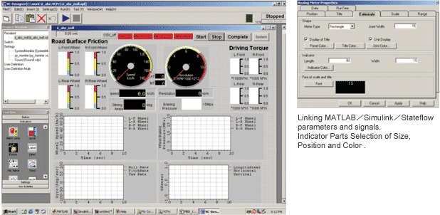
We offer AD-VirtualConsole as graphical user interface for the realization of RPT and/or HIL testing systems. You can configure customized graphical user interfaces very easily such as the instrument panel similar to the one in a real car and real-time parameter monitor. (measured values and trend graphs) We configure control panels by arranging GUI Control. We offer Designer environment for the designers and supervisors and Runtime environment for the operators. The test sequence program can be developed by linking with external applications.
Designer Screen / GUI Control Property

MATLAB/Simulink/Stateflow/Real Time Workshop
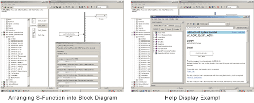
This is the framework of A&D-DSP. Simulink enables the development of control logics by arranging and connecting functional blocks, and the functions, which are not in the pre-configured I/O nor in the standard library, can be integrated as a S-Function in the block diagram.
The Stateflow is the expression of state transitions in a chart diagram format, and can be integrated in the Simulink block diagram. Servo control and/or sequential control can be configured by the combination of Simulink and Stateflow. Real-Time Workshop(Simulink option)converts the block diagram into C-code automatically. (Build).

S-Function
We offer special functional parts group which are not available as standard functional blocks in the MATLAB/Simulink/Stateflow such as Implementation block set and ASP block set.
- Special Real-time Calculation
- Complied with ASAM
- Special Post-processing
- CalculationI/O Controller for A&D-DSP

Implementation Block set includes A/D, D/A, DI/O, CAN, Ethernet, Keyword 2000, Serial, PWM, Encoder, Missing Teeth, Pulse, Crank Angle Sensor, Knock Sensor, Ignition Timing Confirmation Signal, Fuel Injection Timing Signal, Sine-wave Generation, Square-wave Generation, Random-wave Generation and etc.
CANPack
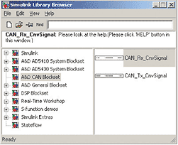
 When you are developing models, which includes CAN communication, "Extraction of the CAN signal value from CAN byte data" or "Build CAN byte data from CAN signal value" can be done very efficiently.
M&C Ladder
We support Ladder Diagram, which is very popular in PLC sequential control development, to develop control logics. After the ladder diagram is developed, it is converted to C-code.

MODEL


- ECU Checker Model
- Engine (PT) Test Bench Model
- Hydraulic Servo Testing System Model
- Simplified Engine Model
- Simplified Transmission Model
- Simplified Vehicle Model
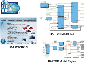
- ABS HILS Model
- EPS HILS Model
- Universal ECU Gasoline Engine Model
- Universal ECU Gasoline Engine Model