Product
Mini Motor Bench
Electric Vehicles (EV) and
Hybrid Vehicles (HEV)
The Mini Motor Bench (MMB) provides a development environment for motor controllers. A motor controller is provided as a flexible Real-Time Rapid Prototyping (RT-RPT) controller device. The system is suitable for control algorithm development and parameter optimization.
Motor controller development
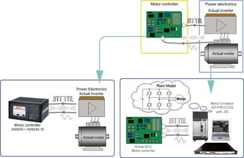
Many motors have been introduced to the market for a variety of uses. There is also therefore a demand for a number of controllers in order to provide optimal control of motors. To match the pace of motor development, controllers must also be developed quickly, and one way to ensure this, while producing durable and effective products, is to develop motors and controllers in parallel. Generally, motor controllers are developed with a HILS system but there is a demand to confirm the developed control algorithm with an actual motor. However, it requires huge investments to prepare a real target motor.
Downsizing the target motor
Preparing a large size motor for motor controller development requires a high capacity of electric power, a rigid design system for withstanding high torque demand and a high running cost. In reality, most users just want to test their motor controller quickly and easily. A&D offers the Mini Motor Bench system as an inexpensive but realistic motor controller development environment with a down sized motor bench system. In general, the main difference between large motors and downsized motors is the difference in their moment of inertia, but this has little influence for the development of controllers. Therefore, confirming the control algorithm with a downsized motor can be considered sufficient for control of motors of larger size as well.
Features of the Mini Motor Bench
All necessary components for motor controller development are prepared. Users are able to trial various motor control algorithms and optimize the number of parameters of the motor controller.
- A brushless DC motor (BLDC) as the target motor
- DC motor for simulating motor load. Torque adjustment is performed by changing the load resistance.
- An inverter circuit and power unit for driving the motor is embedded inside the system.
- A resolver speed signal from the motor and a PWM signal from the RT-RPT controller act as interfaces between the MMB system and the RT-RPT.
Real-Time controller
The RT-RPT system has a wide range of flexibility and can be used for various purposes.
- AD5435: Real-Time Rapid Prototyping system
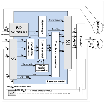
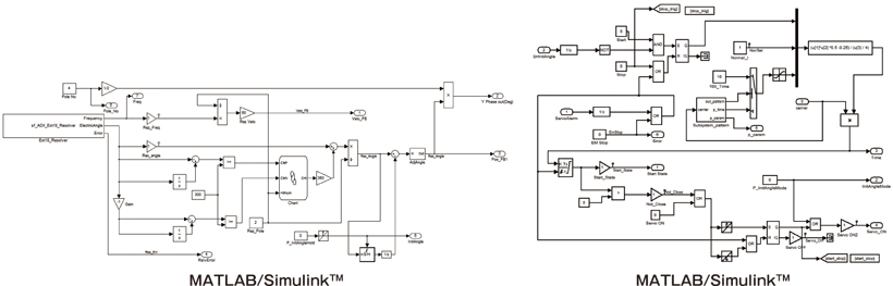
Main unit of the RT-RPT controller has seven option board slots for enhancing the system. Core model is created from MATLAB/Simulink™. - AD5430-18
Specialized board for motor control application (Other option boards are available.)
Application examples
- Motor controllers evaluation
It is possible to connect an actual motor controller to the MMB. Hence motor controllers can be evaluated in a realistic environment. - Motor controller algorithm development
Using a RT-RPT controller, control algorithms can be modified with a MATLAB/Simulink™ model. This is the best fit for motor control engineers. - Educational tool
Together with the compact size of the MMB and RT-RPT controller, they come with basic software that makes the system suitable as an educational tool. - Bench-mark for new development
The control algorithm software and MMB hardware circuit diagram are open to the user. Therefore, users can use this system as a bench-mark and can modify the system by themselves.
Software package
The RT-RPT controller system comes with a control program, so the system can be used immediately. Also users are able to modify the software such as the control algorithm and GUI interface for customization.
Included:
- Circuit diagram and parts list
- Control source code (MATLAB/Simulink™ model)
Includes MATLAB/Simulink™ add-on compiling environment (Please prepare MATLAB/Simulink™ separately.) - GUI building software tool
Design application software (VirtualDSPConsole) is included.
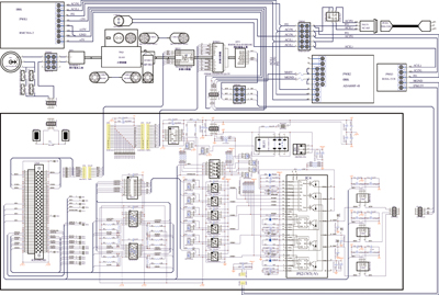
Circuit diagram
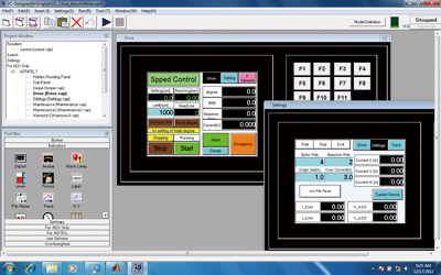
VirtualDSPConsole
Specifications
Mini Motor Bench specifications (reference)
| Power | AC power specification 90 to 260V |
|---|---|
| Current | 2.7A |
| Motor rotation speed | MAX 3000 rpm |
| Motor output | 30W |
| Resolver specification | Can connect to AD5430-18 |
| Carry case size | 4500 mm x 3500 mm x 2000 mm |
Control target (AD5435) specifications
| Memory | SDRAM 512MB |
|---|---|
| OS | RTOS |
| Display | 5.7inch color TFT LCD (with backlight) |
| Operation interface | Resistive touch screen. Customizable function keys |
| I/O slots | For AD5430 series I/O board 7 slots |
| PMC interface | For A&D link or FlexRay 1 slot (option) |
| Peripheral connections | Ethernet, 100base-T FTP server function |
| Power specifications | AC power specification (AD5435A) 85 to 264V DC power specification (AD5435) 12V (6 to 18Vpp) or 24V (16 to 36Vpp) |
| Power consumption | 100VA (AC or DC power) |
| Operation temperature range | 5 to 40°C |
| Operation humidity range | 5 to 90% R.H. (non-condensing) |
| Dimensions | 318(W) x 230(D) x 168(H) mm |
| Weight | About 6.5kg (chassis only) |
Control board (AD5430-18) specifications
| Resolver input | R/D converter Transformation ratio Output impedance Output excitation signal Maximum angle speed |
AU6802NI (made by Tamagawa Seiki) 0.286 / 0.5 10Ω or less 10kHz / 20kHz 240,000 rpm |
|---|---|---|
| Analog input | Number of channels Signal format Sampling frequency Input range Resolution |
4 Differential signal 40kHz (maximum) Can synchronize with PWM carrier wave. ±5V 16 bit |
| PWM output | Number of control axes Output format Output voltage Carrier wave |
6 Differential (UH, VH, WH, UL, VL, WL) 0 to 5V Triangular wave, 20kHz (maximum) |
MATLAB/Simulink are registered trademarks of MathWorks, Inc.